How many channels does a fixed gas detection system need?
One per gas, not one per detector. Eranntex controllers are sized in gas channels, so a detector that measures four gases uses four channels whichever way it is wired.

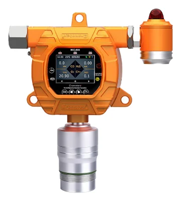
The wiring changes how those channels arrive. On 4–20 mA, a multi-gas detector such as the GTYQ-MIC-600 gives one analog loop per gas, so a four-gas unit needs four analog inputs and is ordered with four analog output channels. On RS485 the same detector uses one pair of wires and one Modbus address, and sends all four readings and alarm states over it. The controller still manages those as four channels.
Six four-gas detectors therefore make 24 channels. Wired on 4–20 mA they need 24 analog inputs, which only the MIC-1000 and MIC3000 offer. On RS485 they take six addresses and fit within any of the four MIC controllers.
Channel capacity is not the only thing that sets the number of controllers; the site layout does too. On one chemical-plant project, 98 single-gas CO detectors were spread over 16 explosion-protected MIC2000-Ex controllers on RS485. Most controllers served a dozen or so detectors in one area; some served a single detector. None was close to its 128-input limit.
4–20 mA or RS485: which signal for each point?
All five Eranntex fixed detectors provide three-wire 4–20 mA and RS485 Modbus RTU as standard, and all four MIC controllers accept both, so any of these detectors can be paired with any MIC controller on either signal. Eranntex handles combinations outside the published outputs as custom development.
| Aspect | 4–20 mA | RS485 Modbus RTU |
|---|---|---|
| Wires per detector | One loop per gas | One shared bus pair for many detectors |
| What it carries | Live concentration over the 0–100% range; fault and over-range shown as defined currents below 4 mA or above 20 mA | Live concentration, low and high alarm states and fault state for every gas |
| Where alarm limits sit | Usually in the DCS, or in the controller's relay logic | In the detector and controller; the DCS reads the states |
| Typical use | Direct input to a DCS or PLC analog card | Many points on one cable to a MIC controller, or to a DCS over Modbus |
Eranntex detectors use one factory-default set of fault and over-range current values across the range. The values are given in the technical documents and can be changed at order to match a DCS analog input configuration. A broken loop is a separate case: the current falls to near zero, so the input card sees a wiring fault rather than a detector status.
For Modbus integration, Eranntex supplies the register map for the specific controller or detector model with the shipment, or earlier on request when the DCS is being configured during design. It is not a public download because it has to match the hardware and firmware version.
HART is optional on all five detectors: HART 5 on the GTYQ-MIC-500S and GTYQ-MIC-600, HART 5 or HART 7 on the GTYQ-MIC-500S-CB-IR2, and HART on the MIC-500S-CB and MIC-600-CB. It is used with a DCS or a handheld communicator; the MIC controllers do not list HART as an input.
Decide where the alarm acts
Eranntex supports four arrangements, and the choice depends on who has to react to an alarm:
- Detectors to a MIC controller, with local actions. The controller drives beacons, fans or valves from its relays.
- Detectors to a MIC controller, then to a DCS or plant network. The controller handles local alarms and passes data upward over RS485 Modbus, or over optional 4–20 mA, Ethernet or wireless outputs.
- Detectors straight to a DCS. No Eranntex controller is used; the DCS reads 4–20 mA or Modbus.
- A mix. Some points go to a MIC controller and some go directly to the DCS.
Every MIC controller sets low and high alarm limits separately for each channel, has three alarm levels, and can link each channel to up to three relay outputs. The relays are programmable, so one detector can start a fan at the first level and close a valve at the second. The controllers also check each input line for open and short circuits.
Each detector has its own dry-contact relays: up to two on the MIC-500S models and MIC-600-CB, up to three on the GTYQ-MIC-600. These can switch a local beacon even where the signal goes straight to a DCS.
Field example: ammonia alarms on refrigerated fishing vessels

Each vessel in the batch had five freezer holds and a compressor space to watch, with fans and a sprinkler system to be switched on alarm. Each received single-gas ammonia detectors on RS485 and one MIC3000. The customer's specification had asked for 0–1000 ppm everywhere. Eranntex engineers set the freezer holds to 0–100 ppm, because the risk there is exposure of people entering the hold, and the compressor space to 0–100 %LEL, with the low alarm at 20 %LEL starting the sprinklers through a controller relay. Each detector was wired with a twisted pair for RS485 and a two-core power cable. Power-loss cover was left to the vessels' own UPS because the hold time had not been defined. The shipyard's contractor installed the system with remote guidance from Eranntex.
How to size the alarm controller
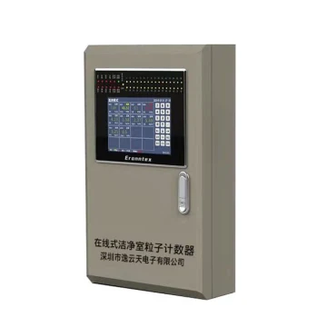
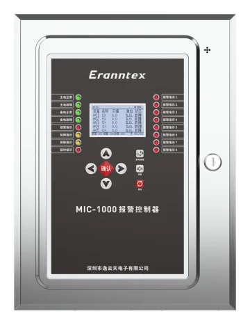
Start with where the controller will be mounted. The MIC-1000-Ex and MIC2000-Ex are explosion-protected and designed to sit in the hazardous area itself, for example on a skid or tank farm without a control room. Where a safe-area control room exists, Eranntex recommends a standard controller there: it costs less, and opening it for adjustment does not need a hazardous-area work permit.
Capacity then decides the model. All four take 4–20 mA and RS485 inputs at the same time.
| Controller | Mounting | 4–20 mA inputs | RS485 inputs | Relays (standard / optional) | Backup power |
|---|---|---|---|---|---|
| MIC-1000 | Wall, safe area | 1–8, 16, 24 or 32 | Up to 128 | 4 + 1 common / 8, 12, 16, 24 or 32 | 12 V DC, 7 Ah, standard |
| MIC-1000-Ex | Wall, explosion-protected | 1–8 | Up to 128 | 4 + 1 common / 8, 16, 24 or 32 | 24 V DC, 5 Ah, optional |
| MIC2000-Ex | Wall, explosion-protected | 1–8 | Up to 128 | 4 + 1 common / 8, 16, 24 or 32 | 24 V DC, 5 Ah, optional |
| MIC3000 | Wall, safe area, 9-inch touchscreen | 1–8, 16, 24 or 32 | Up to 256; cascaded systems up to 1000 input channels | 8 + 1 common / 16, 24 or 32 | 24 V DC, 5 Ah, optional |
Standard relay contact ratings:
- MIC-1000, MIC-1000-Ex and MIC2000-Ex: 3 A at 32 V DC or 3 A at 220 V AC; common alarm output 12 A at 32 V DC or 7 A at 240 V AC.
- MIC3000: 3 A at 250 V AC or 3 A at 30 V DC; common alarm output 10 A at 277 V AC or 12 A at 125 V AC.
- Relay assignment and ratings can be customized for a project.
The 128 and 256 figures are the most channels one controller can manage. When a project mixes analog and RS485 inputs, the usable split depends on detector types, bus loading and polling time, so Eranntex sets the channel allocation from the project's point list and pre-commissions the controller before shipment.
Wiring, power and the hazardous-area interface
Wiring and bus loading
Eranntex engineers usually wire an RS485 detector with one four-core cable: two cores for the 24 V DC supply and two for the RS485 pair, so each run is pulled once. On a multi-building laboratory project this replaced an initial plan of two separate two-core cables.
Electrical loading limits one RS485 bus to about 32–64 detectors in Eranntex practice; larger systems use more bus loops on the controller or RS485 repeaters and hubs. Each detector on a bus needs a unique address from 1 to 128 and the same baud rate as the controller. Addresses can be set through the menu with the infrared remote, and on the CB models also with a magnetic wand, without opening the enclosure. Send a tag list with the order and Eranntex pre-sets the addresses at the factory.
Power
The MIC-1000 is specified at 2.5 W per input and can power all 32 analog detectors from its internal supply, which covers typical electrochemical and catalytic detectors. A separate 24 V DC supply near the detectors is worth adding in three cases:
- cable runs beyond roughly 300–500 m, where voltage drop can leave the detector under-supplied;
- RS485 buses with many detectors, powered in segments while the controller carries only the communication pair;
- sites that need long operation after a mains failure, since the controller's backup battery has limited hold time at full load.
Hazardous-area interface
When detectors sit in a hazardous area and the controller in a safe area, Eranntex recommends fitting a safety barrier or isolating barrier on the safe-area side of each detector circuit, and its engineers size it from the area classification and the detector model before shipment. For an intrinsically safe circuit, such as the RS485 circuit covered by the intrinsic-safety parameters in the GTYQ-MIC-600 certificate, the barrier is part of the certified system and is always fitted. For other circuits, whether it is fitted depends on site conditions.

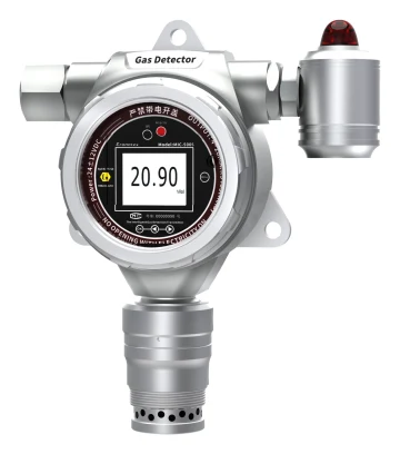
The detector's certificate states its protection type: the GTYQ-MIC-500S family is flameproof (Ex db IIC T6 Gb), and the GTYQ-MIC-600 is certified Ex da ia IIC T6 Ga under CE24.5822X, whose annex includes intrinsic-safety parameters for its RS485 circuit.
For sensing principle and mounting position on oil and gas sites, see the oil and gas page. For whether a project needs fixed monitoring at all, start with How to Define an Industrial Gas Leak Detection Project.
What to send with an enquiry
A point list lets Eranntex size the controller, relays and power in one pass. For each point, the useful columns are:
Enquiry worksheet
Point list for a fixed gas detection system
| Tag or location | Gas | Measuring range | Signal (4–20 mA / RS485 / HART) | Hazardous-area zone |
|---|---|---|---|---|
Entries stay in this page. Preparing text does not submit an enquiry.
Use one row for each gas at each point.
Models: fixed gas detectors · gas alarm controllers · Request a quote